Rubber Expansion Joint Installation Guide: SEE DOCUMENT
Features
- Higher burst pressure ratings vs. AMT Series Rubber Expansion Joints
- Meets the requirements for low lead per NSF/ANSI 372
- Applicable for suction and delivery (discharge).
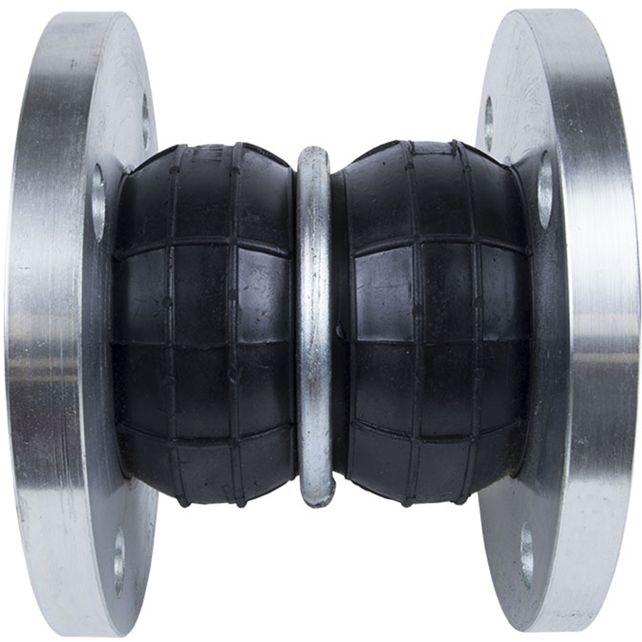
- Designed for greater compression, elongation, and angular movement than the single sphere expansion joint.
- Excellent for absorbing thermal expansion and eliminating sound and vibration.
- Gaskets and packing not required.
- Good electrical insulator.
- Absorbs water pulsation and minimizes water hammering.
- DIN PN10/PN16 drilled flanges available upon request (See DIN Flange section for dimensions)
- Working pressure ratings based on 4:1 safety margin (at 70°F).
Applications
- Pressure piping systems in building equipment and general industrial plants.
- Pump and turbine lines used for power generation plants, industrial machinery and universal pump blowers.
- Feed-water & drainage lines for waterworks & sanitary piping systems.
- Pipelines for industrial plants and shipbuilding yards.
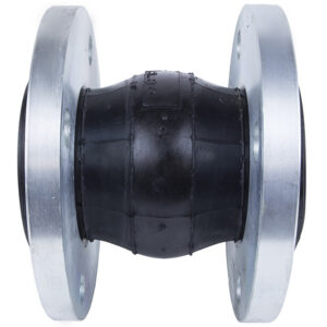
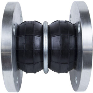
Specifications: Twin Sphere Molded Rubber Expansion Joints (AJT Series)
ALL DIMENSIONS ARE IN INCHES UNLESS OTHERWISE STATED
| API Part Number |
Size |
Face To Face Dimensions |
Allowable Motion Ratings*
Compression |
Allowable Motion Ratings*
Elongation |
Allowable Motion Ratings*
Lateral |
Allowable Motion Ratings*
Angular |
Installation Tolerances
Compression |
Installation Tolerances
Elongation |
Installation Tolerances
Lateral |
Installation Tolerances
Angular |
| AJT0100** |
1 |
5.00 |
2.00 |
1.00 |
1.75 |
35° |
0.13 |
0.13 |
0.13 |
10° |
| AJT0125** |
1.25 |
7.00 |
2.00 |
1.00 |
1.75 |
35° |
0.13 |
0.13 |
0.13 |
10° |
| AJT0150** |
1.5 |
7.00 |
2.00 |
1.00 |
1.75 |
35° |
0.13 |
0.13 |
0.13 |
10° |
| AJT0200** |
2 |
7.00 |
2.00 |
1.00 |
1.75 |
35° |
0.13 |
0.13 |
0.13 |
10° |
| AJT0250 |
2.5 |
7.00 |
2.00 |
1.00 |
1.75 |
35° |
0.13 |
0.13 |
0.13 |
10° |
| AJT0300 |
3 |
7.00 |
2.00 |
1.00 |
1.75 |
35° |
0.13 |
0.13 |
0.13 |
10° |
| AJT0400 |
4 |
9.00 |
2.00 |
1.38 |
1.56 |
35° |
0.13 |
0.13 |
0.13 |
10° |
| AJT0500 |
5 |
9.00 |
2.00 |
1.38 |
1.56 |
30° |
0.13 |
0.13 |
0.13 |
10° |
| AJT0600 |
6 |
9.00 |
2.38 |
1.38 |
1.56 |
30° |
0.13 |
0.13 |
0.13 |
10° |
| AJT0800 |
8 |
13.00 |
2.38 |
1.50 |
1.38 |
30° |
0.13 |
0.13 |
0.13 |
10° |
| AJT1000 |
10 |
13.00 |
2.38 |
1.50 |
1.38 |
30° |
0.13 |
0.13 |
0.13 |
10° |
| AJT1200 |
12 |
13.00 |
2.38 |
1.50 |
1.38 |
20° |
0.13 |
0.13 |
0.13 |
10° |
| AJT1400 |
14 |
13.75 |
2.38 |
1.50 |
1.13 |
20° |
0.13 |
0.13 |
0.13 |
10° |
| AJT1600 |
16 |
13.75 |
2.38 |
1.50 |
1.13 |
20° |
0.13 |
0.13 |
0.13 |
10° |
| AJT1800 |
18 |
13.75 |
2.38 |
1.50 |
1.13 |
20° |
0.13 |
0.13 |
0.13 |
10° |
| AJT2000 |
20 |
13.75 |
2.38 |
1.50 |
1.13 |
20° |
0.13 |
0.13 |
0.13 |
10° |
| AJT2400 |
24 |
13.75 |
2.38 |
1.50 |
1.13 |
20° |
0.13 |
0.13 |
0.13 |
10° |
“*”- Non Concurrent Ratings.
“**”- Sizes ≤ 2″ do not have root rings.
Warning: Do NOT elongate Twin Sphere Molded Rubber Expansion Joints when installing for suction service.
Part Number Structure
| Part Number Section |
Options |
| Type |
AJT = Twin Sphere Flanged Expansion Joint (Steel) |
| Size |
XXXX = Size in inches going out 2 decimal places |
| Body Material |
NE = Neoprene
EP = EPDM
BN = Buna-N/Nitrile/NBR |
| Flange Material |
STL = Steel |
| Class |
150 = 150# Drilling
300 = 300# DrillingP10 = DIN PN10 Drilling
P16 = DIN PN16 Drilling |
| Example |
AJT0200-NE-STL-150 = 2″ Twin Sphere Expansion Joint with Neoprene Body and Steel Flanges with 150# Drill Pattern |
Operating Conditions
| Size Range |
1” – 12” |
14” – 24” & 28″ |
| Operating Pressure |
up to 225 psi (up to 160°F) |
up to 150 psi (up to 160°F) |
| Burst Pressure |
900 psi (at 70°F) |
600 psi (at 70°F) |
| Vacuum Rating* |
26 in/hg |
15 in/hg |
| Operating Temp. Range* |
Neoprene: 14°F- 180°F
EPDM: 14°F- 210°F
Buna-N/Nitrile/NBR: 14°F- 180°F |
Neoprene: 14°F- 180°F
EPDM: 14°F- 210°F
Buna-N/Nitrile/NBR: 14°F- 180°F |
Warnings:
- Pressure ratings listed in the above table are for temperatures up to 160°F. For temperature service above 160°F, please contact API Sales for actual working pressure ratings.
- Limit rods are required in systems that are unanchored and recommended in all other applications.
- Not for use in steam applications.
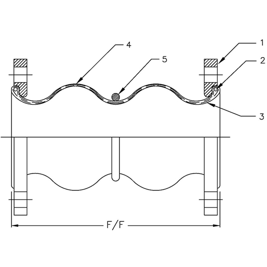
Materials
| Part |
Part Description |
Material |
| 1 |
Flanges |
Mild Steel – Plated |
| 2 |
Reinforcement Cord |
Nylon |
| 3 |
Reinforcing Wire |
Mild Steel |
| 4 |
Tube |
Synthetic Rubber |
| 5 |
Cover |
Synthetic Rubber |
| 6 |
Root Ring |
Mild Steel Plated |
Note II: Customized for flanges ANSI-150, ANSI-300 and DIN