

The Main Parts of a Flange
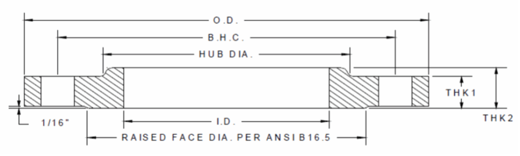
A flange has several defined dimensions that ensure proper fit and sealing in piping systems:
Inside Diameter (ID): The opening that matches the pipe outer diameter.
Outside Diameter (OD): The overall diameter of the flange.
Thickness (T): The height of the flange body.
Hub Diameter (HD): The size of the hub (if present) connecting to the pipe.
Raised Face Diameter (RFD): The sealing surface area for the gasket.
Bolt Circle Diameter (BCD/BHC): The circle on which bolt holes are evenly spaced.
Bolt Holes (BH/BHS): Number, size, and spacing of holes used for fastening.
Chamfer/Bevel (#x45): Edge finishing for easier installation.
Radius (R) / Counterbore (CB): Optional machining features depending on flange type.
Key Specifications of a Flange:
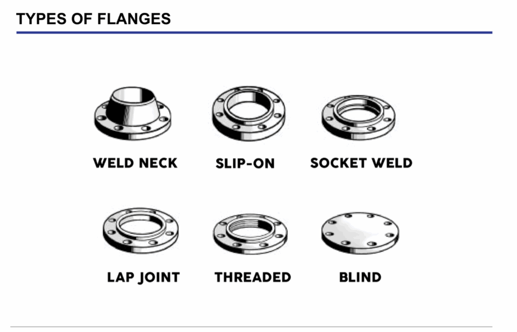
1. Flange Type
- Weld Neck Flange – Features a long tapered hub that is welded to the pipe, which provides excellent strength for high-pressure and high-temperature applications.
- Slip-On Flange – Slides over the pipe and is then fillet-welded. They are easier to install but less strong than a weld neck.
- Socket Weld Flange – Has a socket where the pipe fits before being welded. This flange is typically used for smaller, high-pressure lines.
- Threaded Flange – Screws directly onto pipes with external threads. This type is useful when welding is not possible.
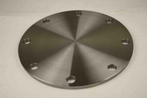
- Blind Flange – A solid plate that closes off the end of a pipe or fitting. These flanges are often used for testing or future expansion.
- Lap Joint Flange – Used with a stub end and allows the flange to rotate for easy alignment, common in systems that require frequent disassembly.
2. Flange Size
Flange size are usually described by the Nominal Pipe Size (NPS) for a standard pipe.
Common Flange Sizes (Example Table)
Nominal Pipe Size (NPS) | Diameter Nominal (DN) | Typical Outside Diameter (in) | Bolt Holes |
½ in | DN 15 | ~3.5 in | 4 |
1 in | DN 25 | ~4.25 in | 4 |
2 in | DN 50 | ~6 in | 4 |
4 in | DN 100 | ~9 in | 8 |
6 in | DN 150 | ~11 in | 8 |
8 in | DN 200 | ~13.5 in | 8 |
12 in | DN 300 | ~16.5 in | 12 |
* Values shown are approximate for ANSI/ASME B16.5 Class 150 flanges
3. Flange Pressure Ratings
- A higher class number = stronger flange, designed to withstand higher pressures and temperatures.
- The actual working pressure depends on the material (carbon steel, stainless steel, etc.) and operating temperature.
- Pressure ratings are important to ensure the flange matches the system requirements and provides safe, leak-free performance.
Example: ANSI/ASME B16.5 Pressure Ratings (Carbon Steel, up to 100°F)
Class | Max Pressure (psi) | Typical Uses |
150 | ~285 psi | General water, low-pressure steam, HVAC |
300 | ~740 psi | Higher pressure water, oil, steam |
600 | ~1,480 psi | High-pressure pipelines, chemical service |
900 | ~2,220 psi | Refineries, power plants |
1500 | ~3,700 psi | High-pressure steam & gas |
2500 | ~6,170 psi | Critical service, extreme pressure |
*Values shown are for carbon steel flanges at 100°F, per ANSI/ASME B16.5.)
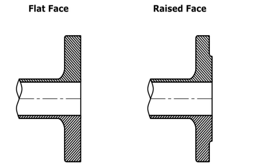
4. Face Type
- Raised Face (RF): Raised face flanges have an area of the face that protrudes. They have less surface area for the gasket to seal off, which allows for a higher pressure seal
- Flat Face (FF): Flat faces have a smooth, flat surface, allowing for easier gasket installation. They are better for low-pressure applications.
- Ring-Type Joint (RTJ): Has a groove that accepts a metal ring gasket for high-pressure applications.
5. Flange Material
1) STEEL (CARBON STEEL)
- Most common flange material
- Higher carbon content than stainless steel for added strength
2) STAINLESS STEEL
- Second most common flange material
- Highest corrosion and rust resistance
3) DUCTILE IRON
- Similar tensile strength to steel, but higher yield strength
- Lower cost than steel, so preferred for instances where the flange doesn’t come in contact with the medium (like with Backing Flanges)
4) ALUMINUM
- High corrosion and rust resistance
- Light weight, so preferred for irrigation and other applications that require movability
Flange Materials and Standards Table
| Material | Standards / Grades | Notes & Applications |
| Carbon Steel | ASTM A36 (plate), ASTM A105 (forged) | Strong and widely used for high-pressure and high-temperature service, including waterworks. |
| Stainless Steel | ASTM A182 (F304, F316), ASTM A240 (plate) | Excellent corrosion resistance; used in chemical, food, and water industries. |
| Ductile Iron | ASTM A536 | Cost-effective with good strength; common in waterworks fittings and backing flanges. |
| Aluminum | ASTM B241 (pipe), ASTM B247 (forgings) | Lightweight and corrosion-resistant; used in marine and irrigation applications. |
| Alloy Steel | ASTM A182 (F11, F22, etc.) | Chrome-moly alloys; high strength at elevated temperatures. |
| Nickel Alloys | ASTM B564 (Inconel, Monel, Hastelloy) | Extreme corrosion and temperature resistance; used in offshore and chemical service. |
| Cast Iron | ASTM A126 (gray iron) | Low-pressure applications; less common in modern flange use. |
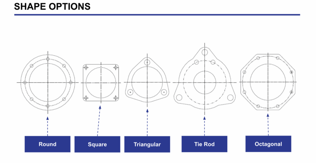
6. Flange Shape Options
Common Flange Shapes
| Shape | Description | Typical Applications |
| Round | The most widely used flange shape, designed to align with standard pipes and fittings. | General industrial, oil & gas, chemical, and waterworks service. |
| Square | Square profile with bolt holes at the corners; useful when attaching to square equipment or non-round pipe systems. | Pumps, valves, custom fabrications. |
| Triangular | Compact flange shape with three bolts; lightweight design. | Low-pressure applications, irrigation, lightweight piping. |
| Tie Rod | Flange with additional rod holes that allow tie rods to pass through, improving strength and alignment. | Expansion joints, piping systems requiring reinforcement. |
| Octagonal | Eight-sided flange offering increased bolt distribution and stability. | Specialty piping, heavy-duty or non-standard installations. |