
We start the process by receiving raw material.
When material arrives, it first goes through receiving inspection. Our receiving inspector performs an initial check per the work order, measuring two points on the material to verify callout dimensions. This confirms that the raw stock matches the order and ensures machining feasibility before it enters production. At the same time, our team files the MTR certifications, the work order, and all associated paperwork tied to that job. Once everything is verified and documented, the material is released and passed on to the machine shop for processing.
Typical Machining Process
Material handling and setup
Once it reaches the machine shop, we organize and separate the parts so they’re easier to access with the forklift. Spacers are placed around the flanges every 8 inches so the material is easier to handle. Fork extensions are used for larger parts so we can safely load them onto the machine. When it’s time to set one up, we position it between two of the jaws. Larger parts typically require two people to guide the flange to the center of the machine: one calls out from the side while the forklift operator lines it up to the center.
Plywood panels are set up around the machine as chip guards. They help contain debris and keep the shop floor clean and safe.
Finding centerline and stabilizing the cut
At this stage, the operator provides a rough estimate of the center and then uses an indicator to dial it in precisely. Many raw forgings have slag on the OD (outer diameter) and/or the ID (inner diameter), so we clean it up enough to prevent it from interfering with the indicator gauge.
The gauge helps the operator find the true centerline. The closer you get to zero runout, the better your chances of cleaning the material evenly and efficiently. If the material is slightly egg-shaped and shows, for example, 0.100 inches of runout, we split it 0.05” one way and 0.05” the other to ensure full cleanup. Once centered, we use jack screws underneath the part to control vibration. Center support is critical for a stable cut when the distance between the jaws is wide.
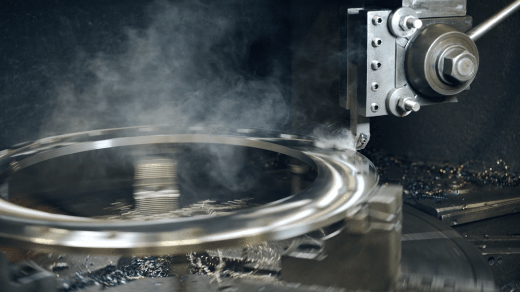
Turning and facing (OD, face, ID)
Before cutting begins, the operator enters the part number and specifications into the system. The operator measures the raw diameter and compares it to the finished size on the print. The first pass is typically a rough pass to establish a clean diameter. Once the surface is cleaned, the operator measures again to determine exactly how much material remains. From there, additional rough passes may be taken before finishing with a final pass to achieve the required surface finish. Everything is driven by the print, including the specific finish the customer calls out.
We normally cut the OD first, then face the surface. The order matters. If you finish the face first and then cut the OD, chips can roll up and scrape across the finished surface. Cutting the OD first protects the final finish. After the initial rough pass, we measure again. We remove excess material and bring the size closer to the final size to achieve a consistent diameter. From there, additional roughing passes are followed by a final finish pass.
For most jobs like this, we have four primary tools set up:
- One for cutting the OD
- One for roughing the face
- One finishing tool
- One ID tool that also functions as a chamfer tool
These four tools cover the majority of our work. If something unusual is called out, such as an oversized chamfer, we may switch to a different insert. We primarily use carbide inserts. The finishing insert has a neutral angle, allowing it to handle chamfers and finishing cuts without constant tool changes. When finishing the ID, we apply cutting oil to prevent chip drag to ensure a smooth surface. During roughing, oil isn’t as critical, but during finishing, it protects the machined surface. Chip control is always important. We adjust speeds, feeds, and depth of cut so chips break into manageable pieces rather than forming long coils.
After completing the first side, partial OD, full face, and full ID, we flip the flange. We then blend the OD and machine the raised face. The raised face is typically 0.060 to 0.062 inches above the base surface. When flipping the part, we use cardboard or other soft material underneath it to protect the serrations and finished surfaces. At this stage, the part still has cutting oil on it. Final cleaning happens later in the process.
Drilling stage
Next, the part moves to the drilling stage. We use a three-jaw lifting clamp to move the flange, wrapping contact points in protective material to avoid surface damage. The three clamps are positioned in a triangle for stability. At the drill station, the operator stages the part and determines the proper clamp and standoff positions. Aluminum blocks are used beneath the workpiece because they’re softer than steel and won’t damage the machined surfaces.
Before drilling, we probe every part to confirm 100 percent centerline accuracy. The probe establishes the centerline along both the X and Y axes and references the top surface along the Z axis. We use drills with indexable carbide inserts. When an insert edge wears out, we rotate it rather than replace the entire tool. Using coolant extends the insert’s life and improves drilling performance.
We begin by drilling pilot holes, or small witness marks, to verify:
- Bolt hole circle diameter
- Hole count
- Spacing
- Correct drill size
It also confirms that the part is sitting flat and that the holes won’t interfere with the support blocks. Once verified, we proceed with full-depth drilling. We typically drill the first hole, stop, measure it, and confirm the diameter before completing the full pattern.
Even if chamfers aren’t explicitly called out, most prints require removing burrs and sharp edges. A light chamfer accomplishes that while also making bolt installation smoother and improving handling safety. The front-side chamfer is completed on the machine. The backside is deburred with pneumatic chamfer tools fitted with carbide inserts to achieve a clean, uniform finish.
After drilling and chamfering, the part is flipped again for backside cleanup, and the completed part is set aside.
Inspection and traceability
Then it moves to inspection. Two machinists complete the first and last article checks, and a supervisor then performs a final inspection before the part moves to the warehouse for stamping and packaging.
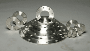
We inspect the completed parts to verify:
- Bolt circle diameter
- Hole diameter
- Hole count
- Concentricity
Concentricity ensures that the ID centerline is aligned with the bolt circle centerline. We check this in four quadrants and typically hold within .030 inches. Once the inspection passes, the parts are thoroughly cleaned, coolant and oil are removed, and they are staged for shipment.
After machining is complete, we also verify that the heat numbers match the documentation. This ensures full traceability of materials back to the original certification. We then stamp the required part information onto the flange, so it remains permanently identifiable.
Pre-Shipping Process
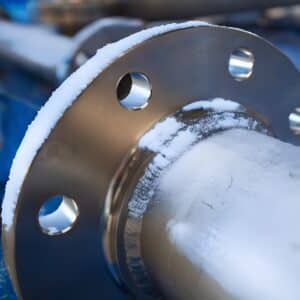
Before anything leaves the building, we prepare it for shipment based on size, weight, material, and other customer-requested packaging requirements. For flanges larger than 53×53-inches, we build custom pallets to properly support the load. Parts are securely strapped, foam-wrapped, and shrink-wrapped to protect them throughout transit.
For stainless steel flanges, we place cardboard between each flange to protect the serrations. If the flanges weigh more than 150 pounds, we also use wooden spacers between them to prevent metal-to-metal contact. For carbon steel flanges weighing over 150 pounds, we also use wooden spacers for separation and protection. Smaller flanges, typically under 3 inches, are boxed.
By the time the product ships, it has been inspected multiple times, by multiple people, documented for traceability, properly marked, and packaged to arrive at its destination in the same condition as it left our shop.
Watch the full process
API International Flange Experts
Our sales team at API International can answer any questions about your flange requirements and guide you toward the best solution for your system. You can also explore our full range of flanges in our online product catalog, or contact us for custom flange options designed to meet your project specifications. Get connected with a dedicated sales representative today, or call us at 503.692.3800.