
1. What Are ANSI/ASME Flanges?
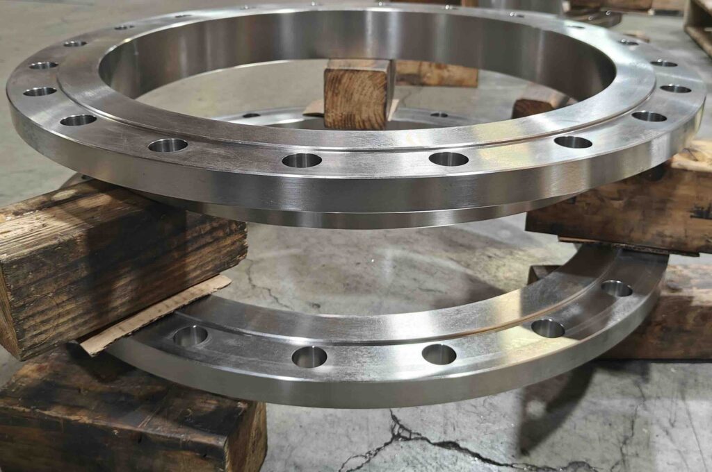
An ASME/ANSI flange is a forged metal component with a machined face and a bolt-circle pattern that allows two pipe ends to be joined with bolts and a gasket. ASME/ANSI flanges comply with the ASME’s B16 Standards Committee series standards. They are manufactured with consistent dimensions, tolerances, pressure-temperature ratings, and material specs. The standard provided compatibility across different manufacturers and systems.
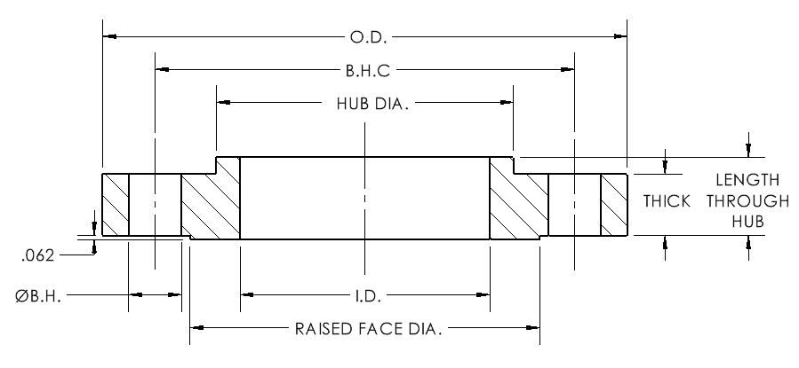
Core Flange Dimensions and Parts
| Parameter / Part | Definition | Role / Purpose |
|---|---|---|
| Inside Diameter (ID) | Bore that matches the pipe’s outer diameter | Supports flow continuity and a correct fit |
| Outside Diameter (OD) | Overall flange size | Affects bolt hole circle and flange strength |
| Flange Thickness (T) | Body thickness | Affects strength, pressure rating, and rigidity |
| Bolt Circle Diameter and Bolt Holes (BCD / BH) | Bolt pattern for fastening flanges together | Important for uniform load distribution |
| Hub or Neck (on some types, for example Weld Neck) | Helps distribute stress into the pipe body | Provides a smooth transition from pipe to flange |
| Sealing Face (Raised Face, Flat, RTJ, etc.) | Machined face where the gasket contacts | Important for sealing integrity |
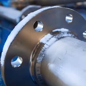
2. Components of a Flange Connection
A bolted flange joint is made up of several elements which work together to maintain integrity:
- Flange Faces: The mating surfaces that compress a gasket between them to create a seal; they may be flat face, raised face, or ring-type joint, depending on the application.
- Gasket: A gasket is placed between serrated flange faces to create a seal between two joined pieces, and it must be compressed to the correct stress to maintain sealing under pressure and temperature changes.
- Bolts, Studs, Nuts, and Washers: These fasteners provide the clamp load that compresses the gasket and holds the joint together; proper tightening is necessary for uniform pressure.
- Alignment and Flatness: The flange faces must be parallel, properly aligned, and free of defects to avoid leaks and ensure correct gasket seating.
- Lubrication: Lubrication on the bolt threads reduces friction and ensures that torque is effectively translated into bolt preload.
- Bolts, Nuts, and Washer Coatings: Fasteners may be coated (such as zinc-plated or hot-dip galvanized) to add protective layers, extending their service life in corrosive environments.
3. Working Principle of ANSI/ASME Flanges
Bolting Mechanism Steps:
Flanges are welded or threaded to the pipe ends.
A gasket is placed between the machined flange faces.
Bolts tighten in a star/cross pattern to create even pressure.
The gasket compresses and fills minor machined serrations.
A pressure-tight, leak-resistant seal is formed.
Bolt tension counteracts internal pipe pressure
4. The Role of the Gasket in Flange Function
The job of the gasket is to create a fluid-tight barrier between joined flange connections.
Common Gasket Types for ANSI/ASME Flanges
| Gasket Type | Description | Pressure Range | Typical Use |
|---|---|---|---|
| Spiral Wound | Stainless steel windings w/ filler | Medium–High | Oil & gas, steam lines |
| Ring-Type Joint (RTJ) | Solid metal ring, high compression | Very High | High temp/pressure applications |
| Non-Asbestos Sheet | Fiber-filled composite | Low–Medium | Water, air, general industrial |
| PTFE Gasket | Chemical-resistant polymer | Low–Medium | Chemical and corrosive service |
! Without a gasket, a flange cannot seal, regardless of bolt torque or flange class.
5. Flange Face Types Affect How the Seal Works
The design of the flange sealing face affects how well the gasket seals and how appropriate the flange is for certain service conditions.
Comparison Table: Flange Faces
| Face Type | Seal Behavior | Typical Gasket | Applications |
|---|---|---|---|
| Raised Face (RF) | Concentrates compression on small area | Spiral wound | Most industrial systems |
| Flat Face (FF) | Full-surface contact | Full-face gaskets | Cast iron systems |
| Ring-Type Joint (RTJ) | Metal-to-metal groove sealing | RTJ ring | High-pressure, high-temperature |
6. How ANSI/ASME Flanges Work Compared to Other Flange Standards
Flange Standard | Technical Differences in How the Standards Work |
|---|---|
ANSI/ASME (U.S. Industrial Standard) | Designed for high-pressure, high-temperature industrial service per ASME B16.5 (NPS ½–24) and ASME B16.47 (NPS 26–60). Flanges are forged from ASME/ASTM material groups and require high-strength bolting per ASTM A193/A194. Sealing performance depends on precise bolt preload, correct gasket seating stress, and machined flange face types RF, RTJ, or FF. Supports spiral-wound and metal gaskets specified in ASME B16.20. Engineered to withstand cyclic loading, vibration, thermal expansion, and pressure shocks common in petrochemical, power, refinery, and steam systems. |
AWWA (Waterworks Standard) | Intended for municipal and waterworks service up to 300 psi under AWWA C207 (steel flanges), AWWA C228 (stainless-steel flanges), AWWA C110 (Ductile-Iron and Gray-Iron Fittings), and AWWA C115 (Flanged Ductile-Iron Pipe with Ductile Iron or Gray-Iron Threaded Flanges). Manufactured primarily from plate steel or ductile iron, depending on the application. Bolt patterns may align with ASME but often require lower bolt preload, as AWWA flanges use full-face soft gaskets specified for water systems. Typically flat-face (FF) only. Not designed for high temperature or mechanical cycling. Suitable for potable water, wastewater, and low-pressure utility pipelines. |
DIN / EN (European Standard) | Governed by the EN 1092 series for steel and cast iron. Uses metric DN sizes and PN pressure ratings (PN6, PN10, PN16, PN25, PN40, PN63, PN100). Face types include RF, FF, RTJ, and TG (tongue-and-groove), per EN standards. Operating limits defined by temperature-dependent pressure curves in EN 1092. Bolt patterns, tolerances, and surface finishes differ from ASME standards, making it compatible only with DIN flanges. |
JIS (Japanese Industrial Standard) | Based on JIS B2220 covering flange sizes and pressure ratings 5K, 10K, 16K, 20K. Typically lighter-duty, using soft gaskets and FF/RF faces with lower bolt load requirements. Materials and thickness correspond more closely to low-PN DIN flanges than to ASME. Suitable for general industrial systems, cooling water, plant utility lines, and low-temperature service. Pressure-temperature capabilities are limited compared to ASME Class 150–2500. Heavy-duty variants exist but are outside the typical JIS scope. Not intended for high-pressure steam, refinery, or critical chemical service unless specially engineered. |
BS / ISO / Other Regional Standards | Includes ISO 7005-1 (international flange system containing both ANSI/ASME B16 and EN 1092-1 flange standards) and BS 4504 (British Standard, now largely superseded by EN 1092, but still used in legacy systems). |