
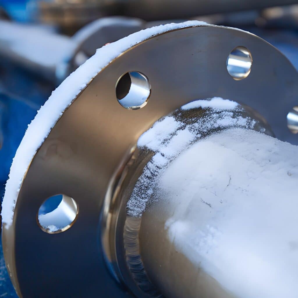
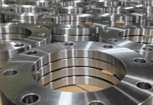
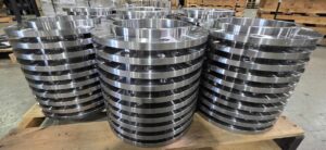
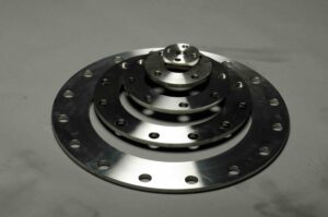

Plate flanges are flanges manufactured from flat-rolled steel plate stock rather than being shaped from heated metal billets through a forging process. They are cut, machined, and drilled from plate stock for use in a wide range of piping systems. In waterworks and many general industrial applications, the “plate flange” people ask for is typically a ring-type slip-on flange. It slides over the pipe outside diameter and is attached with fillet welds at the pipe-to-flange junction.
Since plate flanges exist in several standards and service categories, there is no single universal welding method that applies in every case. Instead, the correct approach is driven by the flange standard, the applicable piping code, and the approved welding procedure for the job. While standards such as AWWA C207, ASME B16.5, ASME B16.47, and EN 1092-1 define flange dimensions, ratings, drilling, facing, and intended use, the project’s welding procedure defines the actual weld detail, process, and acceptance expectations.
Plate Flange Common Standards
Before welding even begins, the flange itself must match the system requirements. In real projects, plate flanges are usually specified under one of these standard families:
- AWWA C207 (waterworks): ring-type slip-on flanges and blind flanges, intended to be attached by welding (per the standard’s welding section).
- ASME B16.5 (NPS systems): covers ratings, materials, dimensions, tolerances, marking, and testing for common pipe flanges and flanged fittings (NPS 1/2 through 24).
- ASME B16.47 (large NPS systems): similar scope for large diameter steel flanges (NPS 26 through 60).
- EN 1092-1 (DN/PN systems): circular steel flanges for DN 10–DN 4000 and PN 2.5–PN 400 (common in Europe and many DN/PN markets).
Welding cannot fix a mismatch in drilling, facing, bore, or geometry. Bolt-hole alignment and gasket sealing depend entirely on the flange being manufactured to the correct standard in the first place. The critical takeaway is that standard defines the flange, but the piping code and the qualified welding procedure (WPS) defines the weld.
The Typical Weld Configuration for a Slip-On Plate Flange
A slip-on plate flange is positioned over the pipe OD and aligned square to the pipe axis, welded at the junction between the pipe and the flange (outside fillet weld). Depending on the piping code and service severity, many projects also require an internal fillet weld at the pipe end for added strength and improved sealing reliability. When using an internal weld, the pipe is typically recessed slightly from the flange face to ensure the weld bead does not interfere with the gasket seating surface.
Typical slip-on plate flange weld layout
| Weld location | What it looks like | Why it’s used | Notes |
|---|---|---|---|
| Outside fillet weld (back side) | Fillet weld at pipe-to-flange outside edge | Primary attachment weld; strength + leak resistance | Most common requirement in slip-on use cases |
| Inside fillet weld (bore side) | Fillet weld inside the flange bore at the pipe junction | Extra reinforcement and improved sealing path control | Used when specified/required; also helps overall joint integrity |
| Tack welds (temporary) | Small welds spaced around the circumference | Holds alignment before final welding | Should be placed to prevent rotation and warping during weld-out |
What Actually Governs the Weld
Welding a plate slip-on flange is not just a shop preference. It is controlled by multiple documents, and each serves a different purpose. The flange standard, such as AWWA C207, ASME B16.5, or ASME B16.47, governs the flange’s sizing, rating, dimensions, and required product characteristics.
The piping code governs whether a slip-on flange is acceptable for the intended service and, in many cases, specifies the required welding configuration. In process piping, ASME B31.3 imposes strict service-based restrictions on slip-on flanges, often requiring double-fillet welding in high-pressure or hazardous applications.
That means the weld is only “right” when it matches three things:
- the engineering design
- the applicable code
- the qualified WPS/PQR for the materials and service
A Practical Welding Workflow
The connection is typically completed with fillet welds at the pipe-to-flange junction. The final weld configuration, including whether it is single-side or double-side, the required weld size, and whether any non-destructive examination (NDE) is required, is established by the project specification and the approved WPS/PQR.
In high-integrity slip-on applications, double-fillet welds may be specified. This involves an outer fillet at the hub-to-pipe junction and an inner fillet at the pipe end, ensuring both structural strength and a reliable seal against the process media.
Typical Welding Steps
| Phase | Description | Purpose |
|---|---|---|
| Surface preparation | Weld areas are cleaned to remove oils, coatings, scale, and moisture | Supports consistent weld quality and reduces the chance of discontinuities |
| Positioning and alignment | The flange is set to the required stand-off, bolt-hole orientation, and squareness to the pipe axis | Helps ensure proper bolt-up and even gasket loading |
| Tack welding and restraint | Tack welds and fixtures are used to maintain location and geometry before full weld-out | Stabilizes alignment and helps limit movement and distortion |
| Final fillet weld deposition | Fillet welds are deposited at the pipe-to-flange junction per the approved procedure | Provides the mechanical attachment required by the design |
| Interpass cleaning | Slag and oxides are removed between passes as required | Helps maintain weld soundness and prevents slag inclusions in multi-pass welds. |
| Final cleaning and protection | The weld area is cleaned and protected or coated as required | Supports corrosion resistance and prepares the assembly for inspection and service |
Why WPS/PQR Discipline Matters
Even though the joint looks simple, the weld variables that matter (joint design, base metals, filler metals, preheat, technique, positions, and even cleaning expectations) are typically controlled through an approved Welding Procedure Specification (WPS) supported by qualification records. The ASME Section IX resource on WPS format shows how a WPS is structured to capture exactly those variables for production welding.
Which Welding Process Is Used?
Most slip-on plate flange welding is performed with common arc-welding processes chosen to match material, shop/field conditions, and the qualified procedure.
| Process | What it is (plain-language) | Why it’s used in flange work |
| GMAW (MIG) | Continuous wire electrode + shielding gas | Fast and versatile; widely used in fabrication environments |
| GTAW (TIG) | Non-consumable tungsten electrode + inert shielding gas; filler added separately if needed | High control and cleanliness; useful where precision and controlled heat input matter |
| SMAW (Stick) | Flux-coated consumable electrode | Often selected when portability and simpler equipment are priorities |
Safety Is Part of Professional Welding Practice
Welding is also hazardous work, and it must be treated that way. Professional flange welding practices include proper PPE, ventilation, and safe work procedures to manage hazards such as welding fumes, UV exposure, burns, and electrical shock. In some applications, especially drinking water systems, materials and components may also need to meet health-related requirements such as NSF.
The Practical Takeaway
Good welding matters, but good flange welding starts before the arc is struck. It starts with the right standard, the right fit-up, and the right procedure. Our sales team at API International specializes in navigating complex flange requirements to ensure your system meets its design specifications. Explore our comprehensive range of plate flanges in our online product catalog, or contact us for custom options tailored to your unique project needs. Get connected with a dedicated sales representative today, or call us at 503.692.3800.