
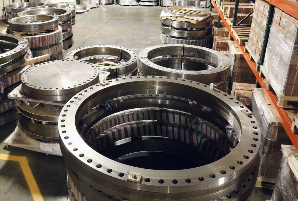

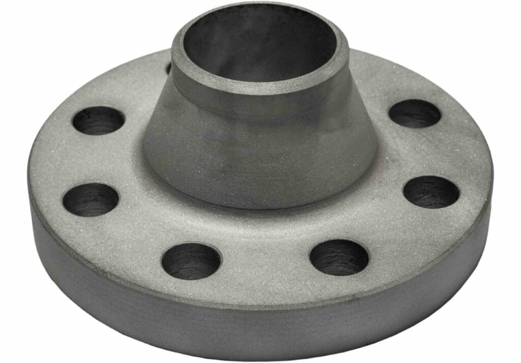
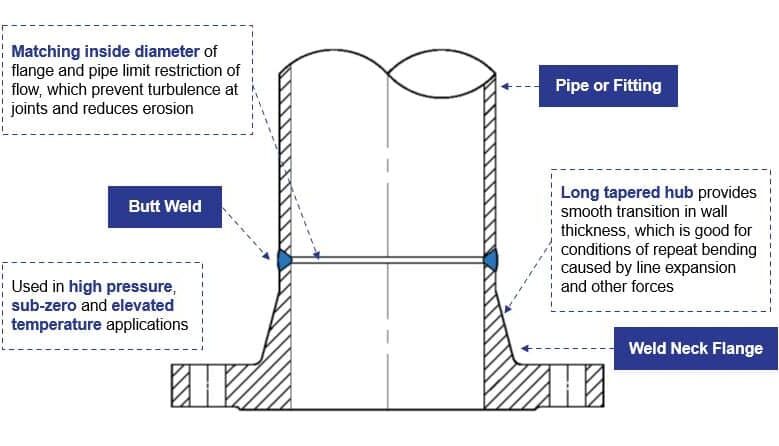
1. Weld Neck Flanges (WN)
Weld neck flanges are a premier choice for high-pressure systems and remain one of the most commonly used flange types. Their defining feature—a long, tapered hub—allows for a seamless butt weld directly to the pipe. This creates a smooth transition that minimizes flow turbulence and erosion. Consequently, they are ideal for critical sectors like oil and gas, where reliability under high pressure is non-negotiable. They are the standard for high-stress, high-temperature, and large-diameter applications.
Best for: High-pressure and high-temperature service
Key features: Long tapered hub, butt-welded connection
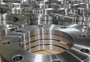
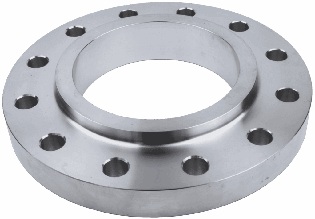
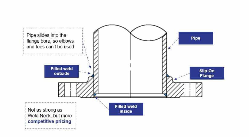
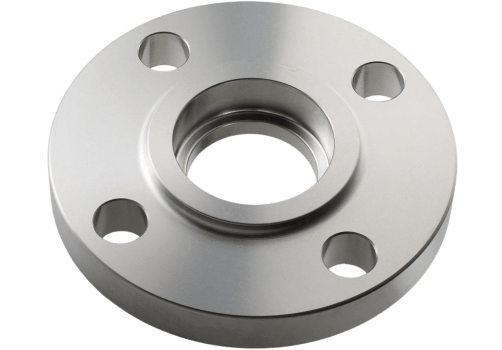
2. Slip-On Flanges (SO)
Key features: Flange slides over the pipe and is fillet-welded on both sides
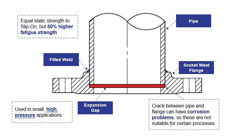
3. Socket-Weld Flanges (SW)
Socket-weld flanges are designed for high-pressure and high-temperature environments, making them a staple in the power generation and chemical processing sectors. They feature a specialized counterbore that allows the pipe to be inserted into a socket, facilitating a clean, single-fillet weld on the exterior. While less common in large-scale piping, they are highly effective for applications where space is limited and are typically the preferred choice for smaller nominal pipe sizes. When used in these smaller diameters, socket-weld flanges serve as a robust, high-performance alternative to both slip-on and weld-neck flanges.
Best for: Small-bore, high-pressure pipelines
Key features: Pipe inserts into a recessed socket; welded only on the outside
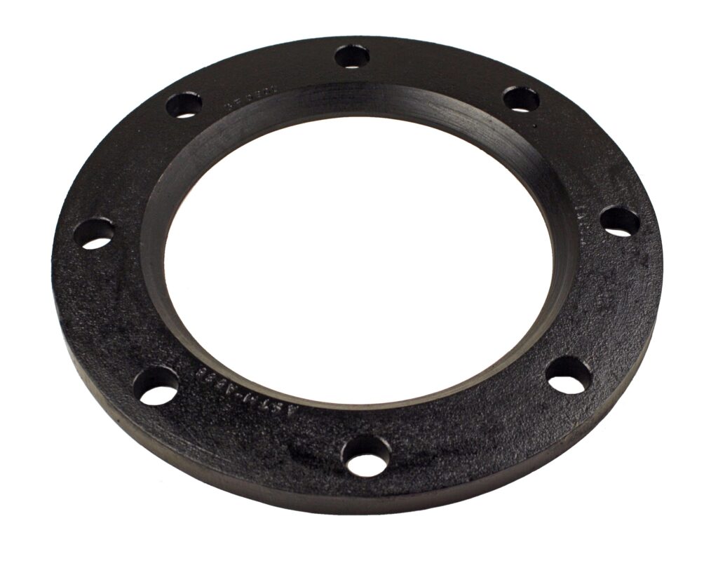
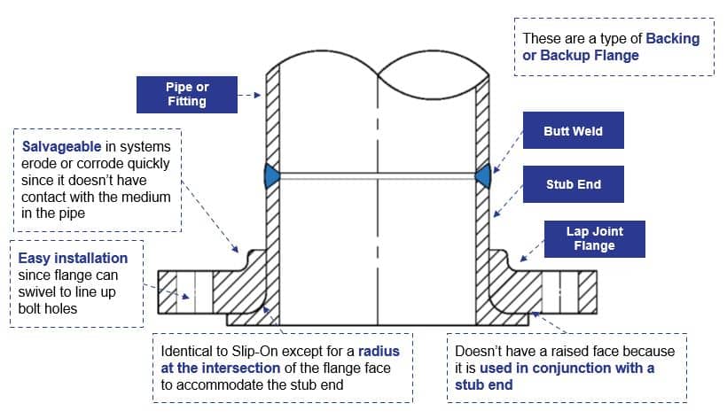
4. Lap-Joint Flanges (LJ)
Lap-joint flanges operate in tandem with a stub end that is butt-welded directly to the pipe. Also referred to as ‘Loose Hubbed’, ‘Van Stone’, ‘Backup’, or ‘Loose Ring’ flanges, they are designed for easy disassembly, making them ideal for systems requiring frequent cleaning or maintenance. This two-piece configuration allows the backing flange to rotate freely, significantly simplifying bolt-hole alignment. Furthermore, this design offers a distinct economic advantage: operators can utilize cost-effective carbon steel for the backing flange while using a high-performance, corrosion-resistant alloy for the stub end, the only component in contact with the process fluid.
Best for: Systems requiring frequent disassembly or corrosion-resistant alloy piping
Key features: Used with a separable stub end; flange does not contact the process fluid
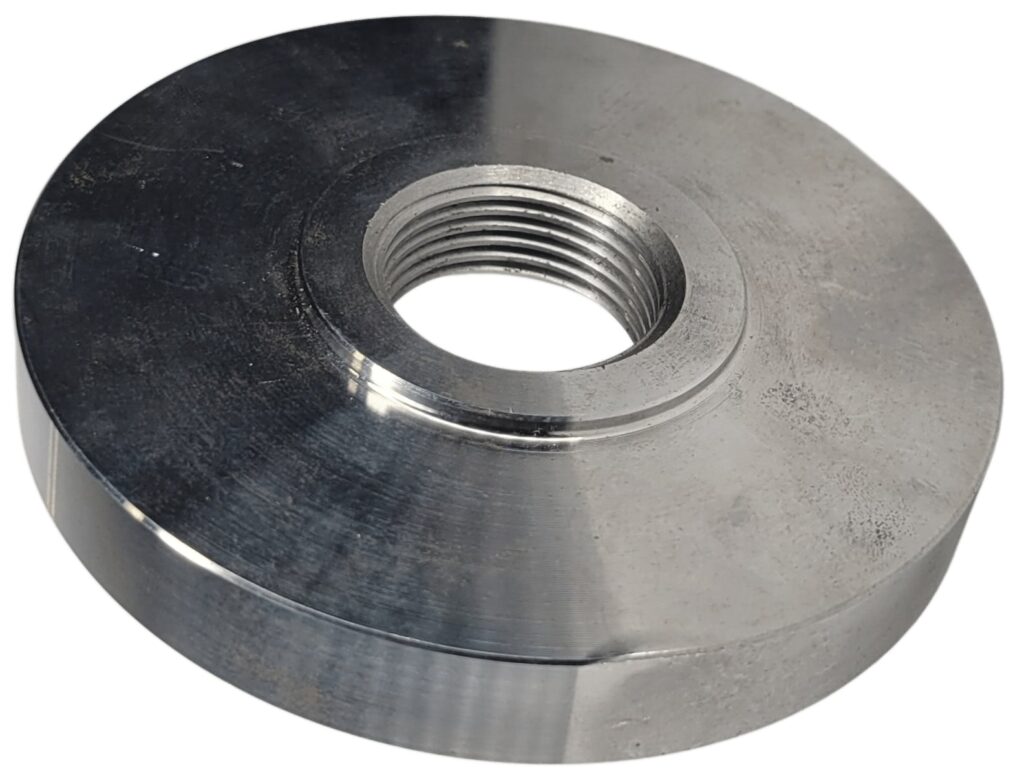
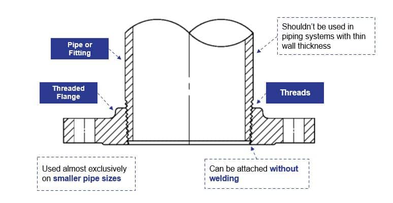
5. Threaded (Screwed) Flanges
Threaded flanges offer a streamlined installation process, making them an essential component for low-pressure, non-critical piping systems. Often referred to as ‘screw’ or ‘companion’ flanges, they feature a female NPT bore that allows for a secure connection to male-threaded pipe without the need for welding. This makes them ideal for environments where welding is hazardous or impractical. While they are frequently used for creating reduced connections, it is important to note that their use is typically limited to smaller diameters and applications where temperature fluctuations are minimal. Beyond the standard NPT form outlined in ASME B16.5, specialized thread styles can also be machined to meet specific project requirements.
Best for: Low-pressure, non-welded systems
Key features: Internal tapered threads that match NPT threads on the pipe
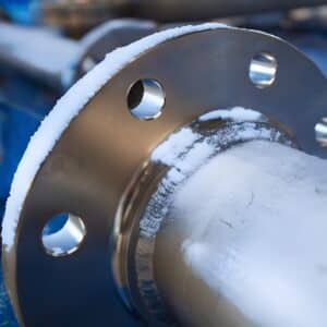
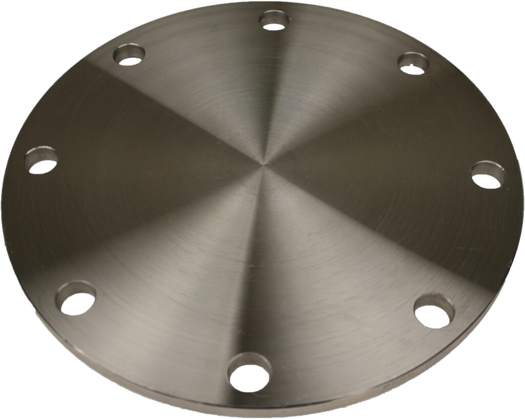
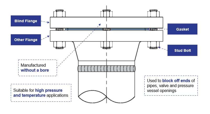
6. Blind Flanges (BL)
Blind flanges serve as the definitive endpoint for a piping system, used to terminate lines or isolate specific process equipment. In industries handling petrochemicals or hazardous materials, they act as a dependable safety barrier, preventing leaks and ensuring worker protection during maintenance or emergency shutdowns. Unlike other flange types, blind flanges are bolted rather than welded, providing easy access for inspections, cleaning, or future system expansions. Since they are subjected to significant bending stress from internal pressure, precise selection and rating are critical. To accommodate these high-stress environments, ASME B16.5 specifies blind flanges in all pressure ratings, from Class 150 up to Class 2500.
Best for: Closing pipe ends, vessel openings, or inspection ports
Key features: Solid flange without a bore
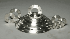
7. Additional Special Flange Types (Industry-Recognized)
7.1 Long Weld Neck (LWN) Flanges
7.2 Orifice Flanges (for flow measurement)
7.3 Reducing Flanges
7.4 Expander Flanges
7.5 Custom Made Flanges
8. Summary Table: Standard ANSI/ASME Flange Types
| Flange Type | Connection Method | Strength / Rating | Common Applications |
|---|---|---|---|
| Weld Neck (WN) | Butt-welded with tapered hub | Highest strength; excellent for cyclic, high-pressure, high-temperature service | Refineries, power plants, steam, critical process piping |
| Slip-On (SO) | Slides over pipe; dual fillet weld | Medium strength; easy alignment and installation | Water systems, utilities, general industrial service |
| Socket-Weld (SW) | Pipe fits into machined socket; external weld | High strength for small-bore, high-pressure lines | Hydraulic lines, steam, chemical injection systems |
| Threaded (THD) | NPT threaded; no welding | Low/medium pressure; good where welding is not possible | Hazardous areas, low-pressure utilities |
| Lap-Joint (LJ) | Used with stub end; loose rotating flange | Medium strength; rotatable; excellent for corrosion-resistant systems | Lined pipe, food processing, alloy systems |
| Blind (BL) | Solid plate with bolt holes | Designed to withstand full pressure without a bore | Pipeline terminations, isolation, pressure testing |
| Long Weld Neck (LWN) | Extended hub; butt-weld | Very high mechanical strength; replaces pipe + weld neck | Pressure vessel nozzles, high-pressure transitions |
| Orifice Flange | Weld neck or slip-on with orifice bore and taps | Designed for flow measurement assemblies | Metering, flow control, instrumentation |
| Reducing Flange | Built-in change of pipe size | Provides integral size reduction without a fitting | Flow transitions, compact pipeline layouts |
| Expander Flange | Increases pipe size at flange connection | Smooth diameter transition; reduces turbulence | Pump suction/discharge, pipeline size changes |