
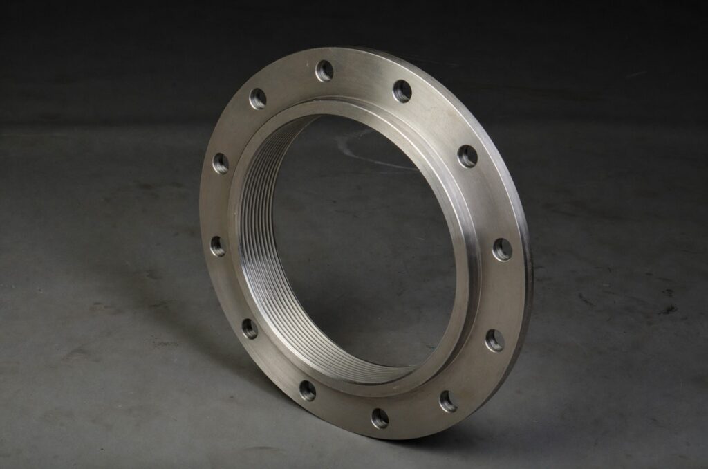

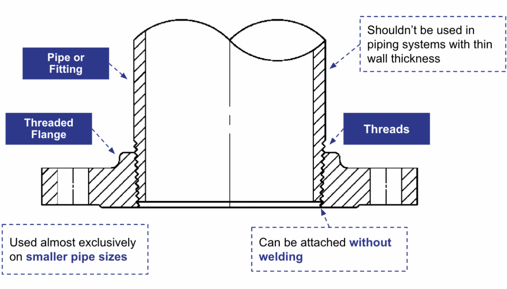
1. What Is a Threaded Pipe Flange and How Does It Connect?
NPT Thread Mechanics: How the Connection Works
| Thread Type | Full Name | Used in Threaded Flanges? |
| NPT | National Pipe Taper | Yes — the only type used for pressure-tight flanged connections |
| NPSC | National Pipe Straight Coupling | No — straight thread for couplings; not for pressure-tight joints |
| NPTR | National Pipe Taper Railing | No — railing fittings only |
| NPSM | National Pipe Straight Mechanical | No — mechanical assembly only; not for pressure sealing |
| NPSL | National Pipe Straight Loose | No — general mechanical use only |
Thread Configuration by Pressure Class
| Pressure Class | Back Face Configuration | Chamfer | Counterbore |
| Class 150 | No counterbore. Threads chamfered to the thread major diameter. Chamfer is concentric with the thread and counts as part of the overall thread length. | ~45° down to thread major diameter | Not present |
| Class 300 and above | Counterbore present on back face. Threads chamfered at approximately 45 degrees to the thread axis, terminating at the counterbore diameter. Both counterbore and chamfer are concentric with the threads. | ~45° to thread axis, terminating at counterbore | Present |
Reducing Flange Threads
Thread Gaging
- Class 150 flanges (chamfer, no counterbore): The inspection reference is the first thread start, unless the chamfer exceeds the thread major diameter. If it does, the reference point is the last visible thread mark on the chamfer cone.
- Class 300 through 2500 (with counterbore): The reference point is the final thread mark on the chamfer cone, which terminates at the counterbore diameter.
Thread Sealant: Always Required
| Sealant Type | Common Name | Typical Application | Code Reference |
| PTFE tape | Teflon tape | Water, gas, air, steam at moderate temperature and pressure | Permitted under ASME B31.3 with correct application method |
| Anaerobic thread sealant | Pipe dope / compound | Hydrocarbons, higher-pressure process piping | Manufacturer data sheet; verify fluid and temperature compatibility |
| PTFE paste compound | Thread sealant paste | Larger diameter threads; irregular or worn thread surfaces | Confirm chemical compatibility with process fluid before use |
2. The Bolted Joint: How a Threaded Pipe Flange Seals
Once the threaded pipe flange is assembled onto the pipe, it connects to the mating companion flange through a standard bolted flanged joint with a gasket between the two faces. This follows the same mechanics as any ANSI/ASME B16.5 flanged connection. The pressure seal is not made by the bolts. The bolts generate the clamp load that compresses the gasket. The gasket itself is what creates the actual pressure seal. Gasket selection, seating stress, and bolt load distribution all directly affect whether the joint leaks.
Gasket Selection for Threaded Pipe Flanges

| Gasket Type | Compatible Face Type | Typical Service | Temp. Limit |
|---|---|---|---|
| Spiral-wound (SW) | Raised Face (RF) | Process piping, steam, hydrocarbons — suitable for all pressure systems up to 2500 psi | Up to 1500°F |
| Solid flat ring (metal) | Raised Face (RF) | High-temp, high-pressure service, critical joints | No practical limit |
| Full-face PTFE sheet | Flat Face (FF) | Water, mild chemicals, food and pharmaceutical service — pressure applications up to 300 psi | Up to 500°F |
| Full-face rubber (EPDM/NBR) | Flat Face (FF) | Water, wastewater, low-pressure utility service — pressure applications up to 300 psi | Up to 250°F |
| Compressed fiber sheet | RF or FF | Steam, water, general industrial, moderate temperature | Up to 700°F |
| Ring joint (oval/octagonal) | RTJ groove | High-pressure refinery, wellhead, Class 900+ | No practical limit |
Bolt and Stud Specification per ASME B16.5
- A193 B7 — the most common stud bolt in industrial piping. Suitable for general process, oil and gas, and steam service.
- A307 Gr. B — carbon steel bolts used in waterworks and low-pressure utility applications.
- A193 B8 — stainless steel studs for corrosive service.
- A193 B8M — molybdenum stainless studs required when flanges are A182 F316 forged stainless steel.
- A193 B7M — chrome-moly studs used in high-temperature steam and sour service applications.
- A194 2H — heavy hex nuts, the standard pairing with A193 B7 studs in most process piping services.
Bolted Joint Assembly Sequence
- Thread assembly: The flange is made up on the pipe to correct NPT engagement per ASME B1.20.1 with thread sealant applied to the male threads.
- Gasket placement: The gasket is centered on the flange face. Gasket type must be compatible with the face type (RF, FF, or RTJ) per ASME B16.5.
- Stud and nut assembly: The stud bolts are inserted through the matching, aligned bolt holes, and the nuts are threaded on until finger-tight. ASME B16.5 specifies bolt and nut materials for each pressure class and service.
- Cross-bolt tightening: The nuts are tightened in a cross-bolt (star) pattern to distribute the clamp load evenly across the gasket. Sequential (circular) tightening around the flange causes uneven gasket compression and leakage.
- Torque to specification: Final bolt torque is governed by the gasket manufacturer’s installation specification and the project engineering procedure.
- Re-torque after initial pressurization: Gasket creep and bolt relaxation after initial pressurization can reduce clamp load. Many specifications require re-torquing after the first heat-up or pressure cycle.
3. How a Threaded Pipe Flange Handles Pressure and Temperature
Example: Pressure-Temperature Ratings by Class and Material Group
| Class | Group 1.1 (A105) – 100°F (psi) | Group 1.1 (A105) – 500°F (psi) | Group 2.2 (F316) – 100°F (psi) | Group 2.2 (F316) – 500°F (psi) |
| 150 | 285 | 230 | 275 | 230 |
| 300 | 740 | 600 | 720 | 600 |
| 600 | 1480 | 1200 | 1440 | 1200 |
| 900 | 2220 | 1800 | 2160 | 1800 |
| 1500 | 3705 | 3000 | 3600 | 3000 |
| 2500 | 6170 | 5000 | 6000 | 5000 |
4. Limitations in Dynamic and Cyclic Service
| Service Condition | Risk Level | Cause | Recommended Action |
|---|---|---|---|
| Steady-state, low vibration | Low | Minimal dynamic loading on thread joint | Standard threaded pipe flange acceptable |
| Vibrating equipment (pumps, compressors) | High | Vibration progressively loosens NPT thread engagement | Specify socket-weld or weld-neck flange |
| Thermal cycling (frequent hot/cold swings) | Medium-High | Thermal expansion and contraction apply cyclic load to threads | Seal weld may be required per ASME B31.3 |
| Cyclic pressure service | Medium | Repeated pressure load fatigues thread sealant and engagement | Review B31.3 service category requirements |
| Steam above Class 300 | High | Combined thermal and pressure cycling; leakage risk over time | Weld-neck or socket-weld preferred above Class 300 |
| Hazardous fluid service (flammable/toxic) | High | Leakage risk unacceptable for Category M fluid per B31.3 | Engineering review required; seal weld likely specified |
ASME B31.3 Requirements for Threaded Connections
- Category D Fluid Service: Threaded connections permitted without additional restriction where service is non-flammable, non-toxic, gauge pressure does not exceed 150 psi, and temperature is between -20°F and 366°F.
- Normal Fluid Service: Threaded connections are permitted but engineering judgment is required for elevated-temperature or high-cycle applications. Seal welds may be required by the project specification.
- Category M Fluid Service: Threaded connections are generally not permitted. Welded connections are required for highly toxic fluid service.
- Seal weld: ASME B31.3 permits and in some cases requires a seal weld over threaded connections in elevated-temperature or critical services. The seal weld eliminates the leakage path through the threads but removes the ability to disassemble the joint.
Size Limitations for Threaded Pipe Flanges
| NPS Range | Threaded Flange Use | Industry Practice |
|---|---|---|
| NPS 1/2 to NPS 2 | Most common range | Standard for utility, instrument, and maintenance connections |
| NPS 2-1/2 to NPS 4 | Common with engineering review | Used in general process and waterworks; torque control important |
| NPS 5 to NPS 6 | Limited use | Only where welding is genuinely not feasible; engineering approval |
| NPS 8 and above | Not recommended | Thread make-up impractical in field; weld connections are standard |
5. Threaded Pipe Flange vs. Other Flange Types
| Flange Type | Connection Method | Welding Required | Pressure Classes (B16.5) | Typical Application | Primary Limitation |
| Threaded | NPT thread onto pipe end | No (seal weld optional) | Class 150-600 typical | No-weld zones, maintenance and instrument connections, small bore | Not for vibration, high-temp cycling, or Class 900+ without derating |
| Socket-Weld | Pipe inserted into socket, fillet weld | Yes (one fillet weld) | Class 150-2500 | Small bore high-pressure service, clean fluids | Crevice at socket base; not for corrosive fluids that trap in crevice |
| Slip-On | Pipe through bore, two fillet welds | Yes (two fillet welds) | Class 150-2500 | General service where easy fit-up and lower cost are priorities | Lower fatigue strength than weld-neck; two welds required |
| Weld-Neck | Butt-welded to pipe with matching bore | Yes (full penetration butt) | Class 150-2500 | High-pressure, high-temp, cyclic, and critical service | Higher cost; bore must match exact pipe schedule |
| Lap Joint | Stub end welded; flange rotates freely | Yes (on stub end) | Class 150-2500 | Lined pipe, dissimilar metals, alignment-critical connections | Lower rating than weld-neck; stub end material must match pipe |
| Blind | No bore; closes end of piping | No | Class 150-2500 | Line isolation, pressure testing, future connection provisions | Not a pipe-joining flange; no flow path |
| Flange Type | Connection & Welding | Pressure Class | Application & Limitation |
|---|---|---|---|
| Threaded | NPT thread onto pipe end; No welding (seal weld optional) | Class 150–600 typical | No-weld zones, maintenance and instrument connections, small bore. Not for vibration, high-temp cycling, or Class 900+ without derating |
| Socket-Weld | Pipe inserted into socket; one fillet weld | Class 150–2500 | Small bore high-pressure service, clean fluids. Crevice at socket base; not for corrosive fluids |
| Slip-On | Pipe through bore; two fillet welds | Class 150–2500 | General service, easy fit-up, lower cost. Lower fatigue strength than weld-neck |
| Weld-Neck | Butt-welded to pipe; full penetration weld | Class 150–2500 | High-pressure, high-temp, cyclic service. Higher cost; bore must match pipe schedule |
| Lap Joint | Stub end welded; flange rotates freely | Class 150–2500 | Lined pipe, dissimilar metals, alignment-critical. Lower rating than weld-neck |
| Blind | No bore; no welding | Class 150–2500 | Line isolation, pressure testing. Not a pipe-joining flange |
Conclusion
Threaded Pipe Flanges FAQs
What are threaded flanges?
What is the difference between a threaded flange and a slip-on flange?
When are threaded flanges the right choice?
How to install a threaded flange?
Quick Guide:
Prepare the pipeline and clean threads.
Apply a thread sealant or Teflon tape.
Screw the flange onto the pipe until snug.
Use a wrench to tighten as needed.
Align flanges for gasket seating.
Insert gasket.
Install bolts evenly.
Perform a final torque check.