


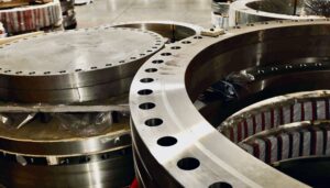

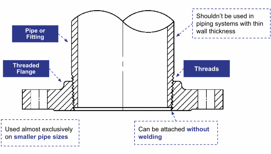
1. What Is a Threaded Flange?
How Is a Threaded Flange Different from Other Flange Types?
| Flange Type | Attachment Method | Welding Required? | Typical Use |
|---|---|---|---|
| Threaded (Screwed) | Screwed onto male-threaded pipe | No | Small-bore systems; typically up to Class 600 utility or hazardous zones |
| Weld Neck | Butt-welded to pipe | Yes — full penetration | High-pressure, critical service |
| Slip-On | Slipped over pipe, fillet welded | Yes — fillet weld | General service, easier alignment |
| Socket Weld | Pipe inserted into socket, fillet welded | Yes — fillet weld | Small bore, high pressure |
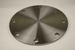
| Blind | Bolted to mating flange — no pipe | No | Line termination / inspection |
| Lap Joint | Stub end welded; flange free-floating | Yes — stub end weld | Systems needing frequent dismantling |
2. What Is a Companion Flange?
3. Key Things to Know Before Using Threaded Companion Flanges
3.1 Governing Standards
- ANSI/ASME B16.5 — Pipe Flanges and Flanged Fittings (NPS 1/2 through NPS 24). This is the primary dimensional and pressure-temperature rating standard for most threaded flanges. It covers classes 150 through 2500, materials, facing types, and bolt/stud requirements.
- ANSI/ASME B16.47 — Large Diameter Steel Flanges (NPS 26 through NPS 60). Covers Series A and Series B flanges for large-bore applications.
- ASME B1.20.1 — Pipe Threads, General Purpose (Inch). Defines the NPT thread form used in the bore of threaded flanges.
- MSS SP-44 — Steel Pipeline Flanges. Covers larger-diameter flanges and is referenced within ASME B16.47 Series A.
3.2 Pressure Classes
| Class | Approx. Max. Pressure @ 100°F (Carbon Steel, Group 1.1) | Typical Applications |
| 150 | 285 psi (19.6 bar) | Low-pressure steam, water, utilities |
| 300 | 740 psi (51.1 bar) | General process piping |
| 600 | 1480 psi (102 bar) | Moderate-pressure hydrocarbon service |
| 900 | 2220 psi (153 bar) | Higher-pressure process systems |
| 1500 | 3705 psi (255 bar) | High-pressure hydrocarbon, steam |
| 2500 | 6170 psi (425 bar) | Very high-pressure critical service |
3.3 Pressure–Temperature Ratings
| Temperature (°F) | Temperature (°C) | Max. Pressure (psi) |
| -20 to 100 | -29 to 38 | 740 |
| 200 | 93 | 680 |
| 400 | 204 | 655 |
| 600 | 316 | 600 |
| 800 | 427 | 550 |
3.4 Flange Face Types
- Raised Face (RF): The most common face type. A raised circular area on the flange face concentrates gasket compression.
- Flat Face (FF): The seating surface is flush with the flange OD. Used when mating with flat-face flanges on equipment such as cast iron valves or pumps. Full-face gasket required.
- Ring-Type Joint (RTJ): A machined groove cut into the face accepts a metallic ring gasket. Used in high-pressure and high-temperature applications. Not common for threaded flanges.
3.5 Dimensions and Nominal Pipe Sizes (NPS)
| NPS | Flange OD (in) | Bolt Circle (in) | No. of Bolts | Bolt Size (in) | Flange Thick. (in) |
| 1/2 | 3.50 | 2.38 | 4 | 1/2 | 0.44 |
| 1 | 4.25 | 3.12 | 4 | 1/2 | 0.50 |
| 2 | 6.00 | 4.75 | 4 | 5/8 | 0.62 |
| 3 | 7.50 | 6.00 | 4 | 5/8 | 0.69 |
| 4 | 9.00 | 7.50 | 8 | 5/8 | 0.75 |
| 6 | 11.00 | 9.50 | 8 | 3/4 | 0.88 |
3.6 Materials and Material Groups
| Material | ASTM Grade | Typical Service |
|---|---|---|
| Carbon Steel | A105 | General process, oil, gas, water |
| Stainless Steel 304 | A182 F304 | Corrosive service, food, pharma |
| Stainless Steel 316 | A182 F316 | Marine, chloride, high-temp corrosion |
| Chrome-Moly (Alloy) | A182 F11 / F22 | High-temp steam, refinery |
| Duplex Stainless | A182 F51 | Offshore, sour service |
4. How Threaded Flanges Work in Piping Systems
The Bolted Joint
- Fastening: Studs or bolts pass through matching bolt holes.
- Torquing: Nuts are tightened in a cross-bolt sequence to distribute load evenly.
- Sealing: Gasket material and construction must be selected based on fluid, temperature, and pressure — spiral wound (SW), ring joint (RTJ), compressed fiber, or full-face rubber, depending on service.
Limitations in Dynamic and Cyclic Service
- ANSI/ASME B16.5 restricts the use of threaded flanges in certain elevated-temperature and cyclic-pressure applications.
- Many engineering specifications (including ASME piping codes) require a seal weld on top of the threaded connection in critical or high-temperature services.
- Threaded flanges are generally limited to pipe sizes NPS 2 and smaller in high-pressure services, with NPS 4 being a practical upper limit for most utility applications.
5. What's Better for Sealing? Threaded vs Socket Weld Flanges
| Criterion | Threaded Flange | Socket Weld Flange |
|---|---|---|
| Welding required? | No (can add optional seal weld) | Yes — fillet weld required |
| Sealing mechanism | NPT thread taper + sealant compound | Fillet weld (full seal) |
| Vibration resistance | Lower — threads can work loose | Higher — welded joint is rigid |
| Thermal cycling | Moderate — thread sealant degrades | Good — weld tolerates thermal stress |
| Ease of disassembly | High — can be unthreaded if no seal weld | Low — weld must be cut to remove |
| Use in hazardous fluid service | Restricted or prohibited in many codes | Generally permitted with weld inspection |
| Corrosion at joint | Crevice corrosion risk in thread roots | Crevice risk in socket bore; mitigated by gap control |
6. Quick-Reference Summary: Threaded Companion Flanges
Parameter | Details / Range |
Governing Standard | ANSI/ASME B16.5 (NPS 1/2–24); ANSI/ASME B16.47 (NPS 26–60) |
Thread Standard | ASME B1.20.1 (NPT) – standard tapered pipe threads. |
Pressure Classes Available | 150, 300, 600, 900, 1500, 2500 (Note: ratings reduced vs weld-end in class 900+) |
Common Pipe Size Range | NPS 1/2 to NPS 4 (practical limit); up to NPS 6 in low-pressure utility |
Face Types | Raised Face (RF) most common; Flat Face (FF); Ring-Type Joint (RTJ) for Class 600+ |
Common Materials | ASTM A105, A182 F304/F316 (SS), A182 F11/F22 (Alloy Steel), A182 F51 (Duplex) |
Welding Required? | No for standard installation; optional seal weld for critical/high-temp service |
Primary Advantages | No-weld installation; ease of disassembly; suitable for hazardous-atmosphere work zones |
Primary Limitations | Susceptible to leakage under vibration/thermal cycling; restricted in hazardous fluid codes at elevated pressure; not used for wellhead service |
Key Sealant Requirement | PTFE tape or liquid thread sealant (anaerobic compound) on male threads; seal weld if required by code |
Typical Markets / Industries | Oil & gas utilities; water treatment; compressed air; instrumentation; HVAC; small-bore process piping |