

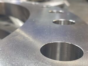
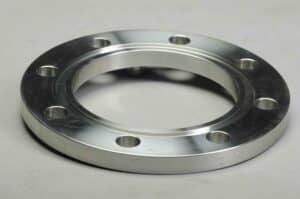
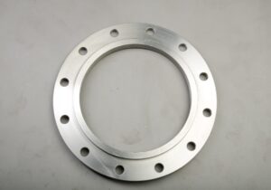
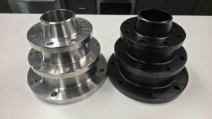
Connecting a weld neck flange to pipe requires a full-penetration butt weld, which provides the joint’s strength and structural integrity. Because the connection depends on weld quality, proper preparation, alignment, and procedure qualification are essential requirements. This guide explains the welding process step by step and outlines the standards that govern its execution.
Surface Preparation
Before welding starts, both the flange hub and the pipe end need inspection and cleaning. Each component must be checked for defects such as cracks, warpage, or corrosion. Once the inspection is complete, the mating surfaces should be cleaned with a wire brush or an appropriate solvent to remove dirt, grease, rust, and paint. Surfaces that are contaminated or poorly prepared can compromise weld integrity, regardless of how carefully the weld is performed.
Bevel and Joint Preparation
A weld neck flange is manufactured with a beveled end that mates with a similarly beveled pipe end to form a V-groove. This groove allows full weld penetration through the joint, creating a strong and reliable connection. Three dimensions define that groove:
Element | Typical Range | Notes |
Bevel angle | 30–37.5° per side (60–75° included) | ASME B16.5 commonly references 37.5° per side |
Root face (land) | 1.0–2.0 mm (1/32– 1/16 in.) | Small unbeveled portion at the base of the groove |
Root gap (root opening) | 1.5–3.0 mm (1/16–1/8 in.) | Essential variable recorded in the WPS and qualified via PQR |
These values are typical rather than fixed, as the project’s welding procedure specification (WPS) establishes the actual joint details. ASME Section IX does not define joint dimensions. Instead, groove design and root spacing are treated as nonessential variables, meaning they are documented in the WPS and may be changed through a revision without requiring requalification of the welding procedure. The procedure qualification record (PQR), in contrast, documents the test weld data that supports and validates the WPS.
Alignment and Tack Welding
The flange is positioned square to the pipe axis, with a consistent root gap around the full circumference. Tack welds are then applied at intervals, commonly at four points 90 degrees apart. These welds hold the assembly in place while alignment is checked and adjusted before the full welding begins. Alignment is critical at this stage. Misalignment introduces stress concentration at the joint and can cause bolt-up problems when the mating flange is installed.
Welding Process and Filler Metal
Several arc welding processes are suitable for weld neck flange connections. Gas Metal Arc Welding (GMAW/MIG) is a faster process, commonly used on carbon steel and thicker sections. Gas Tungsten Arc Welding (GTAW/TIG) is often preferred for critical or high-purity applications where its finer control typically produces a higher-quality weld, particularly for the root pass.
On multi-pass welds, cleaning between passes (interpass cleaning) removes slag and spatter. This step helps maintain weld soundness and prevent slag inclusions.
Preventing Distortion
Heat input during welding can cause warping, particularly in thinner-walled pipe and smaller flanges. Bolting the flange to a mating flange or clamping the assembly to a flat steel plate acts as a heat sink and restrains the joint against distortion. Controlling weld sequence and interpass temperature on larger welds serves the same purpose.
Inspection and Acceptance
After welding, the joint should be examined. The piping code, the service conditions, and the project specification set how much examination is needed. This includes whether Non-Destructive Examination (NDE), such as radiographic or ultrasonic testing, is required.
Governing Standards
The standard defines the flange. The piping code and the qualified welding procedure define the weld.
- ASME Section IX — governs welding procedure and welder qualification. The WPS lists the essential, nonessential, and (when required) supplementary essential variables. The PQR records the test weld that qualifies the procedure.
- ASME B31.3 — the Process Piping Code, governs the design, fabrication, examination, and testing of the piping system the weld becomes part of.
- ANSI/ASME B16.5 and B16.47 — define the dimensions, tolerances, ratings, and welding-end details of weld neck flanges. ANSI/ASME B16.5 covers flanges from NPS ½” through NPS 24″, while ANSI/ASME B16.47 covers flanges from NPS 26″ through NPS 60″. B16.5 also includes the standard weld-end bevel that the pipe preparation must match.
Weld Neck vs. Slip-On: Why the Weld Matters
A weld neck flange uses a single full-penetration butt weld, or complete joint penetration weld (CJP), that joins the beveled hub directly to the beveled pipe end. A slip-on flange works differently. The flange slips over the pipe, and the joint is made with both an inner and an outer fillet weld. A socket weld flange accepts the pipe into a recessed socket and uses a single fillet weld on the exterior.
The weld neck’s tapered hub transitions smoothly to the pipe wall. This spreads stress across the hub and weld area, and it minimizes stress concentration and flow turbulence. The full-penetration weld also carries load more efficiently and has higher fatigue resistance under cyclic loading. That is why weld neck flanges are generally specified over slip-on flanges in high-pressure or fatigue-sensitive service. ASME B31.3 also places service-based restrictions on where slip-on flanges can be used.
Conclusion
Welding a weld neck flange correctly starts with proper bevel and root gap preparation, along with careful alignment before tack welding. A welding procedure qualified in accordance with ASME Section IX, effective distortion control during welding, and the examination required by the project specifications are equally important. Together, these factors contribute to the integrity of the finished joint and its ability to perform as intended under the specified pressure and temperature conditions.
API International supplies weld neck flanges machined from A105 forged carbon steel and A182 and 304/316 forged stainless steel, meeting ANSI/ASME B16.5 and ANSI/ASME B16.47 standards. Explore the full range in our online product catalog, or contact us for custom machining on nonstandard sizes and configurations. Get connected with a dedicated sales representative today, or call us at 503.692.3800.
Frequently Asked Questions
What type of weld connects a weld neck flange to pipe?
A full-penetration butt weld, made through a beveled V-groove machined into both the flange hub and the pipe end. This differs from the fillet welds used on slip-on or socket weld flanges.
What bevel angle is standard for weld neck flange welding?
A bevel angle of 30 to 37.5 degrees per side is typical, giving a 60 to 75 degree included angle. The standard bevel on ANSI/ASME B16.5 weld neck flanges is 37.5 degrees per side.
What root gap should be used when welding a weld neck flange?
Root gap typically falls between 1.5 and 3.0 mm (1/16 to 1/8 inch). ASME Section IX does not fix an exact value. The root gap is documented on the welding procedure specification (WPS) as a nonessential variable and set by the project's welding procedure.
Can MIG welding be used on a weld neck flange?
Yes. GMAW (MIG) is a viable and comparatively fast process for weld neck flange connections, particularly on carbon steel. TIG welding is often preferred for critical applications, especially for the root pass, because it offers finer control and weld quality.
What standard governs weld neck flange welding procedures?
ASME Section IX governs welding procedure and welder qualification. ASME B31.3 governs the process piping system the weld is part of, and ANSI/ASME B16.5 defines the standard weld-end bevel for the flange.