
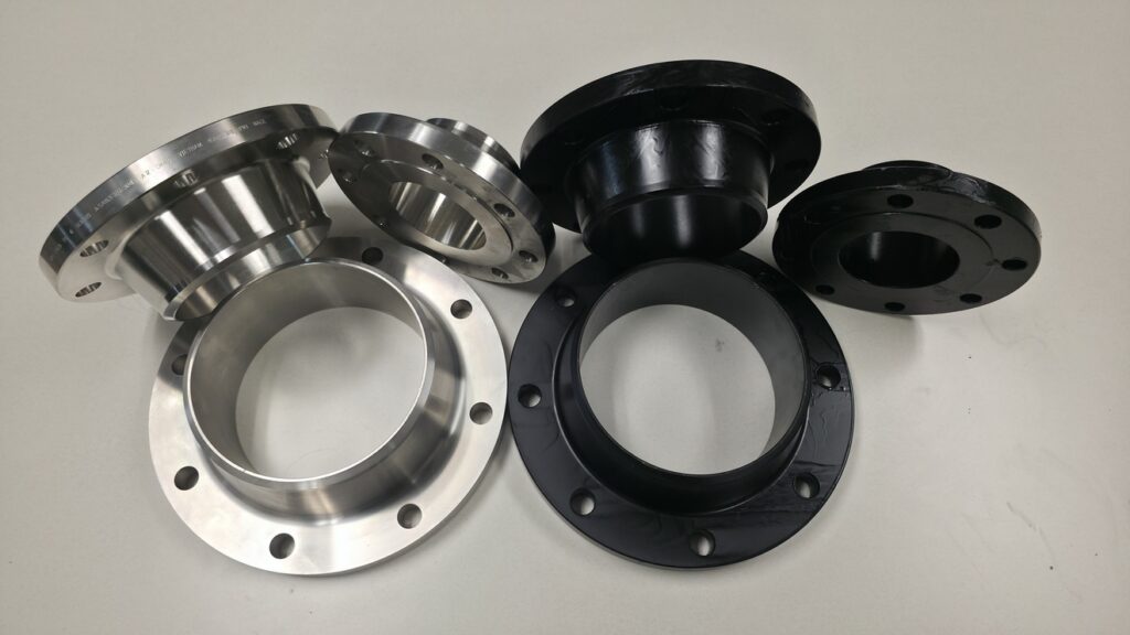
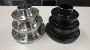
Understanding Weld Neck Flanges
Basic Dimensions for Weld Neck Flanges
| Pressure Class | OD (inches) | Flange Thickness (inches) | Hub Dia. (inches) |
| 150# | 3.5 – 48 | 0.44 – 2.12 | 1.9 – 23.6 |
| 300# | 3.9 – 51 | 0.62 – 2.75 | 2.1 – 25.6 |
| 600# | 4.3 – 55 | 0.81 – 3.62 | 2.3 – 27.5 |
| 900# | 5.0 – 57 | 1.12 – 4.62 | 2.8 – 29.5 |
| 1500# | 5.6 – 61 | 1.44 – 5.62 | 3.1 – 31.4 |
| 2500# | 6.5 – 66 | 2.06 – 7.25 | 3.5 – 33.3 |
How Weld Neck Flanges Are Made
The Manufacturing Sequence
- Raw material preparation. Round or square steel billets in the target grade, typically ASTM A105 for carbon steel or A182 for stainless and alloy steel, are procured with mill certificates documenting chemical composition.
- Cutting to length. Billets are cut to the length needed for the finished flange to minimize waste and ensure consistent volume for forging.
- Preheating. The billet is heated in a furnace above the recrystallization temperature and soaked until uniformly heated, which drops the steel’s strength enough to make it readily deformable.
- Forging. The heated billet is shaped into the rough flange form, most commonly by ring rolling: the billet is upset-forged to compress it axially, pierced to form a hollow blank, then rolled between a main roll and pressure roll to expand it into the final ring shape while continuously refining the grain structure. Larger or non-standard flanges may use open-die forging instead.
- Heat treatment. Depending on class and size, the flange may be supplied as-forged or may require normalizing or tempering to meet the mechanical property requirements of its material grade.
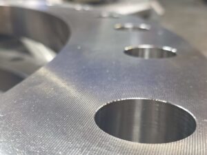
- Machining. The as-forged flange is turned on a CNC lathe to bring the face, hub taper, and outside diameter to final dimensions. Bolt holes are then drilled to match the bolt circle specified by ANSI/ASME B16.5 or B16.47.
- Inspection and marking. Finished flanges are inspected for dimensional accuracy and defects, then stamped with material grade, heat number, and manufacturer identification, with certified mill test reports issued for each heat.
Production Method Comparison
| Production Method | Grain Structure | Typical Use |
|---|---|---|
| Forging (ring rolling or open-die) | Continuous, directional grain flow | Standard ANSI/ASME B16.5 and 16.47 flanges (including weld necks), ASTM A105/A182 |
| Casting | Grain structure set by mold, risk of internal porosity | Specialty shapes, valve bodies, some large fittings |
| Plate cutting | No directional grain refinement | Slip-on and blind flanges in lower-pressure service |
Weld Neck Flange Materials and Standards
Grade | Product Form | Typical Service |
Forged carbon steel | General process and power piping, ambient to 800°F | |
ASTM A182 F304/F304L | Forged stainless steel | Corrosion resistance, moderate-temperature process piping |
ASTM A182 F316/F316L | Forged stainless steel | Higher corrosion resistance, chloride and marine environments |
ASTM A182 F11, F22, F91 | Forged alloy steel | High-temperature steam and process piping above carbon steel limits |
Dimensional Standards by Size
Standard | Size Range | Pressure Classes |
NPS ½” through 24″ | 150, 300, 400, 600, 900, 1500, 2500 | |
NPS 26″ through 60″ | 75, 150, 300, 400, 600, 900 | |
NPS 26″ through 60″ | 75, 150, 300, 400, 600, 900 |
Types and Applications of Weld Neck Flanges
Weld Neck Flange Types
- Standard weld neck — the most common configuration, with a tapered hub of moderate length, available across the full range of pressure classes and sizes.
- Long weld neck — has an extended hub, frequently used as a nozzle on pressure vessels rather than as an inline pipe connection.
- Reducing weld neck — has a hub with a reducing bore, allowing a larger flange to connect directly to a smaller-diameter pipe without a separate reducer fitting.
- Raised-face weld neck — has a small raised sealing area above the bolt circle that improves gasket compression; the standard facing for high-pressure, high-temperature systems.
- Flat-face weld neck — has a flat sealing surface, used in lower-pressure lines or when mating to cast iron equipment.
Where Weld Neck Flanges Are Used
Application | Why Weld Neck Is Specified |
High-pressure pipelines | Tapered neck distributes stress evenly under pressure spikes in industrial, power generation, and chemical lines. |
Steam and thermal systems | Butt weld connection handles thermal expansion without warping or leaking |
Offshore and subsea platforms | Robust weld design withstands vibration, shifting loads, and corrosive conditions |
Large-diameter water mains | Secure, aligned connections minimize flow disruption in municipal and industrial systems |
Chemical and process plants | Long-term reliability and safety in critical process lines |
Weld Neck Flange Welding Procedure
Bevel and Joint Preparation
Element | Typical Range | Notes |
Bevel angle | 30–37.5° per side (60–75° included) | ASME B16.5 commonly references 37.5° per side |
Root face (land) | 1.0–2.0 mm (1/32– 1/16 in.) | Small unbeveled portion at the base of the groove |
Root gap (root opening) | 1.5–3.0 mm (1/16–1/8 in.) | Essential variable recorded in the WPS and qualified via PQR |
Governing Standards
- ASME Section IX — governs welding procedure and welder qualification, requiring essential variables to be documented in a WPS and validated through a PQR.
- ASME B31.3 — the Process Piping Code, governs design, fabrication, and testing of the piping system the weld becomes part of.
- ANSI/ASME B16.5 — defines the flange dimensions, including the standard bevel at the weld end.
Slip-On vs. Weld Neck Flanges
Property | Slip-On Flange | Weld Neck Flange |
Connection to pipe | Pipe slides through bore; two fillet welds | Beveled hub; single full-penetration butt weld |
Stress distribution | Concentrated at fillet weld transition | Distributed along the tapered hub |
Fatigue resistance | Lower under cyclic loading | Approximately 33% – 50% higher under cyclic loading |
Alignment | Easier; bore is slightly larger than pipe OD | Requires precise bevel alignment and root gap control |
Relative cost | Lower | Higher |
Typical use | General service, lower pressure, water and utility lines | High-pressure, high-temperature, critical and cyclic service |
Weld Neck vs. Threaded Flanges
Property | Threaded Flange | Weld Neck Flange |
Connection method | Tapered thread; no welding required | Full-penetration butt weld |
Pressure rating | Low pressure, typically Class 150–300 | Full range, Class 150 through 2500 |
Thermal cycling / vibration | Not recommended; threads can loosen | Well suited; full-penetration weld resists fatigue |
Installation | No welding equipment or procedure required | Requires qualified welding procedure and welder |
Typical use | Low-pressure utility lines, hot-work-restricted areas | High-pressure, high-temperature, critical service |
Why Choose a Weld Neck Flange
Advantage | Why It Matters |
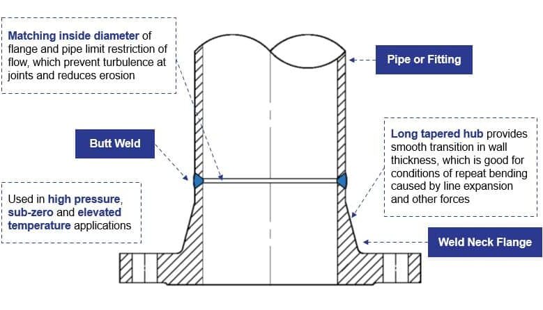
Tapered hub geometry | Spreads stress across a longer section rather than concentrating it at the joint |
Full-penetration butt weld | Carries load through the full material thickness; more fatigue-resistant than fillet welds |
Full pressure class range | Rated from Class 150 through 2500, unlike lower-pressure-limited alternatives |
Cyclic and thermal resistance | Holds up under repeated pressure, temperature, and vibration cycling |
Forged construction | Continuous grain structure through the hub improves long-term reliability |